
powerflex 4 user manual
PowerFlex 4, alongside PowerFlex X, represents a comprehensive cleantech platform, enabling utilities to optimize EV charging and grid flexibility through intelligent energy management.
What is PowerFlex 4?
PowerFlex 4 is a versatile and highly configurable AC drive designed for a broad spectrum of applications, offering precise motor control and enhanced system performance. It’s a core component within the larger PowerFlex ecosystem, working seamlessly with platforms like PowerFlex X. This drive facilitates intelligent energy management, crucial for modern grid demands and the increasing adoption of electric vehicles (EVs).
Specifically, PowerFlex 4 empowers utilities to enable more EV charging and unlock greater flexible capacity for the grid. Through collaboration with companies like WeaveGrid, it demonstrates how distributed energy resource (DER) orchestration at commercial sites can significantly reduce grid stress and support decarbonization efforts. It’s a clean technology solution, making the transition to carbon-free energy a tangible reality.
Essentially, PowerFlex 4 isn’t just a drive; it’s a key enabler of a smarter, more sustainable energy future.
Key Features and Benefits
PowerFlex 4 delivers a multitude of benefits, starting with its ability to monitor, control, and optimize solar, storage, and EV charging assets through the integrated PowerFlex X platform. This provides real-time data access, automated reporting, and maximized performance via adaptive software and hardware – all managed from a single, intuitive dashboard.
Furthermore, the system’s intelligent energy management capabilities reduce grid stress and support decarbonization initiatives. It creates new value streams for both businesses and EV drivers, fostering a more sustainable and economically viable energy ecosystem. The drive’s configuration options allow for tailored solutions, meeting specific application requirements.
Beyond functionality, PowerFlex 4 prioritizes safety and environmental responsibility, exemplified by products like the FSS aerosol extinguisher, boasting low toxicity and environmental safety.
Typical Applications
PowerFlex 4, integrated with PowerFlex X, finds diverse applications in modern energy management. A prominent use case involves partnering with utilities to enable smarter EV charging solutions, unlocking greater flexible capacity for the electrical grid. This is particularly valuable at commercial sites seeking to reduce grid strain and support broader decarbonization goals.
The system also excels in optimizing distributed energy resources (DERs), providing a holistic approach to energy management. Applications extend to automotive suspension systems, utilizing Powerflex polyurethane bushings for enhanced performance and durability – demonstrating the breadth of Powerflex technology.
Moreover, the platform supports projects involving SAAB B205R engines and aerodynamic kits, showcasing its adaptability across various engineering domains. Support resources, including FAQs and direct assistance, ensure seamless implementation across all applications.
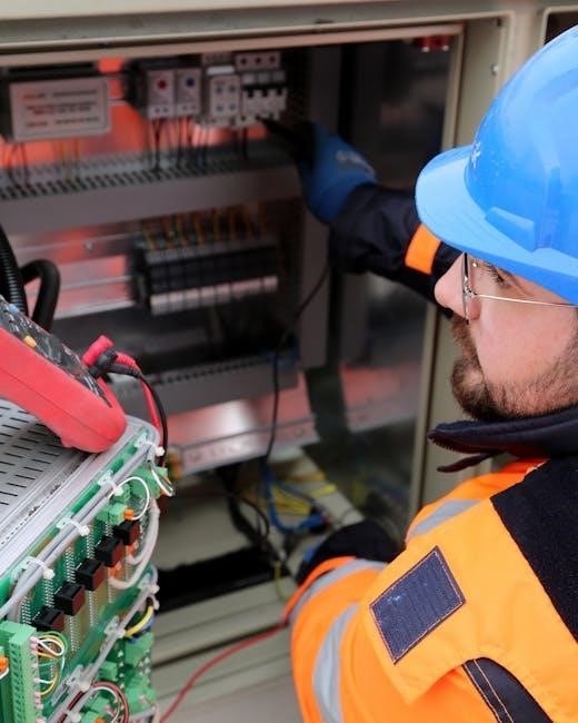
PowerFlex 4 Hardware Components
PowerFlex 4’s core consists of a robust drive enclosure, a sophisticated control board, and a powerful power stack with an efficient heat sink for optimal operation.
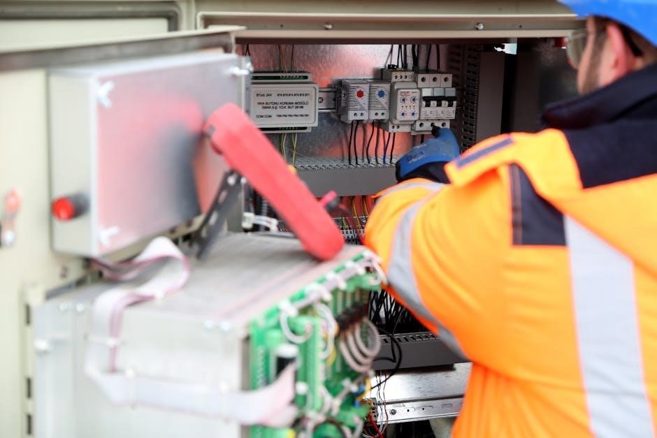
Drive Enclosure and Mounting
The PowerFlex 4 drive enclosure is designed for versatile mounting options, accommodating various industrial environments. It’s constructed from a durable material, ensuring protection against dust, moisture, and other contaminants. Proper mounting is crucial for optimal performance and longevity; therefore, adherence to the manufacturer’s guidelines is essential.
Considerations include adequate ventilation to dissipate heat generated by the power stack. The enclosure’s size and weight should be factored into the mounting structure’s design, ensuring stability and preventing vibrations. Wall mounting, floor mounting, or DIN rail mounting are typical methods, each requiring specific hardware and procedures detailed in the user manual.
Furthermore, maintaining sufficient clearance around the enclosure allows for easy access for maintenance and troubleshooting. Incorrect mounting can lead to overheating, premature failure, and potential safety hazards, so careful planning and execution are paramount.
Control Board and Interface
The PowerFlex 4’s control board serves as the central processing unit, managing all drive functions and communications. It features a user-friendly Human-Machine Interface (HMI) – typically a keypad and display – allowing for parameter configuration, monitoring drive status, and troubleshooting. The interface provides access to a comprehensive menu structure, enabling precise control over motor operation.
The control board supports various communication protocols, including Ethernet/IP and Modbus TCP/IP, facilitating integration into industrial networks. These protocols enable remote monitoring, control, and data logging. Understanding the interface’s navigation and parameter settings is crucial for effective drive programming and operation.
Detailed instructions on accessing and utilizing the control board’s features are provided within the user manual, ensuring operators can maximize the drive’s capabilities and maintain optimal performance. Proper handling and protection of the control board are essential for reliable operation.
Power Stack and Heat Sink
The PowerFlex 4’s power stack, comprised of insulated gate bipolar transistors (IGBTs), is responsible for converting DC power to AC power to drive the motor. These components are critical for efficient and reliable operation, demanding careful handling and protection. The stack’s performance directly impacts the drive’s overall output and efficiency.
A robust heat sink is integrally connected to the power stack, dissipating heat generated during operation. Maintaining adequate cooling is paramount to prevent overheating and potential damage to the IGBTs. Proper airflow and cleanliness of the heat sink fins are essential for optimal thermal management.
The user manual provides detailed guidance on inspecting the power stack and heat sink for signs of damage or contamination. Regular maintenance, including cleaning and verifying proper fan operation, ensures long-term reliability and prevents unexpected downtime.
PowerFlex 4 Parameter Configuration
Parameter configuration within the PowerFlex 4, accessed via its interface, allows precise control of motor and drive behavior, optimizing performance and protection.
Accessing the Parameter Menu
Navigating the parameter menu on the PowerFlex 4 drive is fundamental for customization and optimal operation. Typically, access is achieved through the drive’s Human Interface Module (HIM), often a keypad and display. Begin by ensuring the drive is in Stop mode for safety. Press the ‘Menu’ or ‘Mode’ key – the exact label varies by model – to enter the main menu.
Use the arrow keys to scroll through the menu options until you locate ‘Parameters’ or a similarly named entry. Press ‘Enter’ or ‘Select’ to access the parameter list. Parameters are generally organized into functional groups, such as Motor Parameters (N1/01-N1/06) and Drive Control Parameters (P0/01-P0/05). Further navigation within these groups is again accomplished using the arrow keys. Remember to save any changes made to prevent loss of configuration upon power cycle.
Basic Motor Parameters (N1/01 ⎼ N1/06)
Parameters N1/01 through N1/06 within the PowerFlex 4 define core motor characteristics, crucial for accurate drive operation. N1/01 (Motor Nominal Voltage) sets the motor’s rated voltage, while N1/02 (Motor Nominal Current) specifies the full-load current. N1/03 (Motor Nominal Frequency) defines the frequency at which the motor delivers its rated power.
N1/04 (Motor Nominal Speed) indicates the motor’s speed at rated frequency, and N1/05 (Motor Number of Poles) defines the motor’s pole configuration. Finally, N1/06 (Motor Full Load Torque) sets the motor’s torque at full load. Correctly configuring these parameters ensures the drive provides appropriate voltage and frequency control, optimizing performance and protecting the motor from damage. Incorrect values can lead to instability or reduced lifespan.
Drive Control Parameters (P0/01 — P0/05)
Parameters P0/01 to P0/05 govern fundamental drive behavior within the PowerFlex 4. P0/01 (Drive Enable/Disable) controls overall drive operation, allowing for remote start/stop functionality. P0/02 (Run Forward/Reverse) dictates the drive’s direction of rotation, configurable for various applications. P0/03 (Speed Reference Source) selects the source of the speed command – potentiometer, analog input, or network communication.
P0/04 (Acceleration Time) sets the time taken to reach the target speed, influencing ramp-up smoothness. P0/05 (Deceleration Time) defines the time to slow down, impacting stopping performance. Adjusting these parameters allows fine-tuning of the drive’s response, optimizing for specific load characteristics and application requirements. Careful consideration is vital for safe and efficient operation.

Programming and Operation
PowerFlex 4 programming involves configuring parameters for desired control, utilizing start/stop methods and speed control modes for optimized performance and application needs.
Basic Drive Programming
PowerFlex 4 drive programming initiates with accessing the parameter menu, a crucial step for configuring the drive to match the connected motor and application requirements. This involves setting fundamental parameters like motor voltage, current, frequency, and speed. Understanding these parameters is essential for safe and efficient operation.
Prior to operation, carefully review the user manual, a step-by-step guide designed to facilitate a smooth setup process. The manual details each parameter’s function and acceptable range, preventing potential damage or malfunction. Initial programming focuses on establishing basic motor nameplate data, ensuring the drive accurately controls the motor’s performance.
Furthermore, proper programming includes configuring drive control parameters, defining how the drive responds to start/stop commands and speed references. This foundational programming stage is vital for achieving optimal performance and reliability with your PowerFlex 4.
Start/Stop Control Methods
The PowerFlex 4 offers versatile start/stop control methods, adapting to diverse application needs. These methods include Run Forward, Run Reverse, Stop, and Jog. Utilizing digital inputs, operators can initiate these commands, providing precise control over motor operation. Parameter configuration dictates the behavior of each command, allowing customization for specific processes.
A key consideration is selecting the appropriate stopping method – Ramp to Stop, Coast to Stop, or DC Injection Stop. Each method impacts deceleration time and motor braking characteristics. The user manual details the implications of each choice, guiding optimal selection based on application demands.
Furthermore, the drive supports multiple start/stop sources, including local keypad control, external digital inputs, and network communication via protocols like Ethernet/IP. Proper configuration ensures seamless integration with existing control systems, maximizing operational efficiency and responsiveness.
Speed Control Modes
The PowerFlex 4 provides several speed control modes to optimize performance across various applications. These include Volts per Hertz (V/Hz) control, offering a simple and reliable method for general-purpose applications. Sensorless Vector Control delivers enhanced performance without requiring a speed feedback device, improving torque accuracy and dynamic response.

For applications demanding precise speed regulation, Closed-Loop Vector Control, utilizing an encoder or other feedback device, provides superior performance. This mode enables accurate speed control even under varying load conditions. The user manual details parameter settings for each mode, allowing fine-tuning for optimal results.
Additionally, the drive supports speed ramping profiles, enabling smooth acceleration and deceleration. Adjustable ramp times minimize mechanical stress and improve process control. Selecting the appropriate speed control mode is crucial for achieving desired performance and efficiency.

Communication and Networking
PowerFlex 4 supports diverse protocols like Ethernet/IP and Modbus TCP/IP, facilitating seamless integration into industrial networks for monitoring and control capabilities.
Supported Communication Protocols
PowerFlex 4 drives offer a robust suite of communication protocols designed for versatile integration within diverse industrial automation systems. Key supported protocols include Ethernet/IP, enabling real-time control and data exchange over standard Ethernet networks, crucial for coordinated automation tasks. Furthermore, Modbus TCP/IP provides a widely adopted, open standard for communication, ensuring compatibility with a broad range of Programmable Logic Controllers (PLCs) and Human-Machine Interfaces (HMIs).
These protocols facilitate comprehensive drive monitoring, parameter adjustments, and status reporting. DeviceNet and ControlNet are also supported, catering to legacy systems and specific Rockwell Automation environments. The selection of the appropriate protocol depends on the existing network infrastructure and the desired level of integration. Proper configuration of these protocols is essential for reliable communication and optimal system performance, allowing for seamless data flow and efficient control of motor applications.
Ethernet/IP Configuration
Configuring Ethernet/IP on the PowerFlex 4 involves assigning a static IP address, subnet mask, and gateway, ensuring proper network connectivity. Access the drive’s parameter menu and navigate to the communication settings. Define the IP address within the network’s valid range, avoiding conflicts with other devices. The subnet mask determines the network size, while the gateway facilitates communication outside the local network.
Verify the configured settings using the drive’s built-in diagnostic tools or a network scanner. Proper configuration requires a Rockwell Automation-compatible Ethernet/IP network. Ensure the drive’s EDS (Electronic Data Sheet) file is imported into the PLC’s configuration software for seamless communication. Testing the connection with a simple ping command confirms network reachability. Secure communication is vital; consider implementing appropriate network security measures.
Modbus TCP/IP Setup
Modbus TCP/IP configuration on the PowerFlex 4 enables communication with various industrial controllers and monitoring systems. Begin by accessing the drive’s parameter menu and locating the Modbus TCP/IP settings. Assign a unique Modbus node ID to the drive, ensuring it doesn’t conflict with other devices on the network. Configure the IP address, subnet mask, and gateway, mirroring the Ethernet/IP setup process for network connectivity.
Define the Modbus registers to be accessed, specifying read/write permissions as needed. Utilize a Modbus master device (PLC, HMI, or SCADA system) to initiate communication and verify data exchange. Thoroughly test the setup by reading and writing to various registers. Ensure proper termination and error handling are implemented in the master device. Secure the Modbus connection with appropriate network security protocols.

Troubleshooting and Diagnostics
PowerFlex 4 offers diagnostic tools and fault code solutions; the support team provides assistance via FAQ, email, or phone for any issues.
Common Fault Codes and Solutions
PowerFlex 4 diagnostics incorporate a range of fault codes indicating specific issues within the drive system. Addressing these promptly is crucial for maintaining operational efficiency and preventing further damage. For instance, a frequent code might relate to overcurrent conditions, often resolved by verifying motor and load parameters, or checking for obstructions.
Another common fault involves communication errors, typically requiring a review of the network configuration and cable connections. Low voltage or phase loss faults necessitate inspection of the power supply and wiring. The PowerFlex support team offers detailed troubleshooting guides and assistance interpreting these codes. Regularly reviewing the drive’s status indicators and utilizing the built-in diagnostic tools are proactive steps towards identifying and resolving potential problems before they escalate into significant downtime. Remember to consult the comprehensive user manual for a complete list of fault codes and their corresponding solutions.
Drive Status Indicators
PowerFlex 4 utilizes a comprehensive system of status indicators – LEDs – to convey the drive’s operational state at a glance. These indicators provide immediate feedback on conditions like power availability, drive enabled status, fault presence, and motor running. A solid green indicator typically signifies normal operation, while a flashing green light may indicate the drive is ready to run or in a specific control mode.

Red indicators invariably signal a fault condition, requiring investigation using the diagnostic tools. Amber lights often denote warnings or specific operational states. Understanding the color and flashing patterns of these LEDs is fundamental to quick troubleshooting. The PowerFlex user manual provides a detailed chart mapping each indicator’s meaning, enabling technicians to rapidly assess the drive’s condition and pinpoint potential issues without extensive diagnostics. Regularly monitoring these indicators is a proactive maintenance practice.
Using the Drive Diagnostic Tools
PowerFlex 4 incorporates robust diagnostic tools accessible through its control panel and, more comprehensively, via software connectivity. These tools allow for in-depth analysis of drive parameters, fault history, and real-time performance data. The drive’s diagnostic capabilities enable technicians to pinpoint the root cause of issues, reducing downtime and improving maintenance efficiency.
Accessing fault logs reveals a chronological record of errors, including timestamps and associated parameter values. Real-time monitoring displays critical variables like motor current, voltage, and speed. Utilizing these features, alongside the PowerFlex user manual’s troubleshooting guide, empowers users to resolve complex problems effectively. Furthermore, data logging functionality facilitates trend analysis, identifying potential issues before they escalate into failures, ensuring optimal system reliability and performance.

Safety Considerations
PowerFlex 4 installations demand strict adherence to electrical and mechanical safety guidelines, including proper grounding and emergency stop procedures for personnel protection.
Electrical Safety Precautions
Prior to any installation or maintenance work on the PowerFlex 4, always disconnect and lock out all sources of electrical power to prevent accidental energization. Verify the absence of voltage using a calibrated multimeter before touching any components. Ensure proper grounding of the drive enclosure and all connected equipment to minimize the risk of electrical shock and reduce electromagnetic interference.
Qualified personnel, adhering to relevant electrical codes and standards, must perform all wiring and connections. Use appropriately sized conductors and ensure secure terminations to prevent overheating and potential fire hazards. Regularly inspect wiring for damage or wear, and replace any compromised components immediately. Never operate the drive with damaged cables or connectors. Always utilize appropriate personal protective equipment (PPE), including insulated gloves and safety glasses, when working with electrical systems.
Mechanical Safety Guidelines
When installing the PowerFlex 4, ensure the mounting location can adequately support its weight and withstand potential vibrations. Securely fasten the drive enclosure to a stable surface using appropriate hardware, following the manufacturer’s specifications. Maintain sufficient clearance around the drive for proper ventilation and access for maintenance. Avoid placing the drive in areas exposed to excessive dust, moisture, or corrosive substances.
Inspect all mechanical components, including mounting brackets and cooling fans, for damage before operation. Regularly check fan operation to ensure adequate airflow and prevent overheating. When working near rotating parts, such as fan blades, take necessary precautions to avoid contact. Utilize appropriate lifting equipment when handling heavy components, and follow safe lifting practices. Ensure all covers and guards are securely in place before energizing the drive.
Emergency Stop Procedures
In an emergency situation requiring immediate shutdown of the PowerFlex 4, activate the designated emergency stop (E-Stop) circuit. This will immediately remove power to the drive and connected motor, halting operation. Ensure the E-Stop button is readily accessible and clearly labeled. Regularly test the E-Stop functionality to verify its proper operation and responsiveness.
Following an E-Stop activation, investigate the cause of the emergency before attempting to restart the drive. Address any mechanical or electrical faults that triggered the shutdown. Before restoring power, verify that all personnel are clear of the operating area and that the system is safe to resume operation. Document the E-Stop event, including the cause and corrective actions taken, for future reference and analysis. Prioritize safety and follow established procedures.

Advanced Features
PowerFlex 4, integrated with PowerFlex X, facilitates sophisticated control like PID loops, cam profiling, and sequencing for optimized, complex applications.
PID Control Implementation
PowerFlex 4 offers robust Proportional-Integral-Derivative (PID) control capabilities, enabling precise process regulation. Implementing PID control allows for maintaining desired setpoints in applications like pressure, flow, or temperature control, enhancing system performance and stability. The drive’s parameter structure facilitates easy tuning of PID gains – proportional (Kp), integral (Ki), and derivative (Kd) – to achieve optimal responsiveness and minimize overshoot or oscillation.
Users can configure PID control through dedicated parameters, defining the process variable, setpoint source, and control limits. The PowerFlex 4 provides built-in auto-tuning functions to assist in determining initial PID gain values, simplifying the setup process. Furthermore, advanced features like filter settings and anti-windup mechanisms are available to refine PID performance and prevent instability in challenging applications. Utilizing PID control with PowerFlex 4 ensures accurate and reliable process control, maximizing efficiency and product quality.
Cam Profiling and Sequencing
PowerFlex 4 supports advanced cam profiling and sequencing functionalities, ideal for applications requiring precise, repeatable motion profiles. This feature allows users to define complex speed and torque curves over a defined rotation or time period, mimicking the motion of a mechanical cam. By creating custom cam profiles, the drive can accurately control the movement of machinery in processes like packaging, labeling, or material handling.
Sequencing capabilities enable the execution of multiple cam profiles in a predetermined order, creating automated routines for complex tasks. The PowerFlex 4’s parameter set allows for defining cam points, interpolation methods, and transition characteristics, ensuring smooth and accurate motion. This functionality, often used in conjunction with PowerFlex X for overall system management, enhances productivity and reduces the need for manual intervention. Precise cam profiling and sequencing contribute to improved process control and product consistency.
PowerFlex X Integration
PowerFlex 4 seamlessly integrates with the PowerFlex X intelligent energy management platform, unlocking advanced monitoring, control, and optimization capabilities. This integration allows for real-time data acquisition from the drive, providing insights into performance, energy consumption, and system health. PowerFlex X delivers a centralized dashboard for managing multiple PowerFlex 4 drives, simplifying operation and maintenance.
Through PowerFlex X, users can automate reporting, implement demand response strategies, and maximize the performance of connected assets like solar, storage, and EV charging infrastructure. Adaptive software within PowerFlex X analyzes data and adjusts drive parameters to optimize energy usage and reduce costs. This synergistic relationship between the drive and the platform enables a complete cleantech solution, supporting decarbonization efforts and creating new value streams for businesses. Remote access and control are key benefits of this integration.